WMT CNC Industrial Co., Ltd | All Rights Reserved.Design & Developed by VW Themes

Metal Sheetworking Machines Direct Manufacturer
Metal Sheetworking Machines Direct Manufacturer
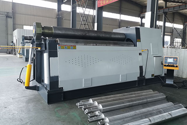
Plate rolling machine can be divided into three-roller and four-roller. The three-roller bending machine can be divided into two types: symmetrical and asymmetrical.
The working principle of the plate rolling machine is a cross-sectional view of the roller of the asymmetrical three-roller plate rolling machine. The roller has a certain length in the axial direction so that the entire width of the plate is bent.
There is an upper roller i at the middle symmetrical position of the two lower rollers, the upper roller can be adjusted in the vertical direction, so that the plate 4 placed between the upper and lower rollers can get different bending radii. The lower roller is active and is installed in a fixed bearing. The motor rotates in the same direction and the same speed through a gear reducer. The upper roller is passive and is installed in a bearing that can move up and down. The adjustment of the rollers on the large plate rolling machine is mechanical or hydraulic, and the small plate rolling machine is often manually adjusted.
When working, the sheet material is placed between the upper and lower rollers, and the upper roller is pressed down to make the sheet material bend between the supporting points. When the two lower rollers rotate, the sheet material moves due to the action of friction, so that the entire sheet material is uniformly bent .
According to the above-mentioned bending principle, it can be known that only when the part of the sheet material and the upper roller is in contact, will the required bending radius be reached. Therefore, the two ends of the sheet have a length that does not touch the upper roller and does not bend, which is called The remaining straight side, the remaining straight side length is about half of the distance between the two lower rollers.
A cross-sectional view of the roller of the asymmetric three-roller plate bending machine. The upper roller is located above the lower roller, and the other roller 3 is on the side, which is called the side roller. The upper and lower rollers are rotated by the same motor. The lower roller can be adjusted up and down, and the maximum distance of adjustment is approximately equal to the maximum thickness of the steel plate that can be rolled. The side rollers are passive and can be adjusted in an inclined direction.
When bending, the sheet material is sent to the upper and lower rollers, and then the lower roller is adjusted to compress the sheet material to generate a certain friction force, and then the position of the side rollers is adjusted. When the upper and lower rollers are rotated by the motor, the sheet material is bent.
The advantage of this asymmetrical three-roller plate bending machine is that the two edges of the plate can also be bent, and the length of the remaining straight edge is much smaller than that of the symmetrical three-roller plate bending machine, which is less than twice the thickness of the plate. Although the sheet metal cannot be bent between the side roll and the bottom roll, the entire bending process can be completed as long as the sheet material is taken out from the bending machine and turned around.
The four-roller plate bending machine is basically similar to the asymmetric three-roller plate bending machine, except that a side roller is added. The bending of the edge of the sheet is performed by two side rollers, which overcomes the problem of the sheet. The trouble of turning and bending on a symmetrical three-roller plate bending machine.
According to the characteristics of rolling deformation, the rolling process can be divided into elastic deformation, elastic-plastic deformation, and pure plastic deformation.
In the initial stage of the bending of the barrel body, the external bending moment is not large, and the value of the internal stress is less than the yield limit of the material. Only cause elastic deformation inside the blank, which is called the elastic deformation stage. When the value of the external bending moment continues to increase, the internal stress exceeds the yield limit and the deformation in the blank deformation zone transitions from elastic deformation to elastic-plastic deformation and pure plastic deformation.
The upper stress of the blank section transitions from the tensile stress of the outer layer to the inner lamination stress, and there must be a layer of metal in the middle, the tangential stress of which is zero, called the stress neutral layer, and its radius of curvature is represented by P. Similarly, the strain distribution transitions from the tensile strain of the outer layer to the compressive strain of the inner layer, during which there must be a layer of metal with zero strain, that is, when the coil deforms, its thickness does not change, which is called the strain neutral layer, and its radius of curvature Expressed by P. This is the basis for accurately calculating the unfolded size of the round blank. That is, the stress neutral layer overlaps with the strain neutral layer and is in the middle of the thickness of the blank. When the deformation is large, the stress-neutral layer and the strain-neutral layer move inward, and the displacement of the stress-neutral layer is greater than that of the strain-neutral layer.
The up and down adjustment of the upper roller is realized by pressing the worm at both ends of the drive screw by the upper roller to drive the worm wheel. The inner hole of the worm wheel is fixed with the nut. There is a lifting screw in the nut. The bearing of the upper roller is Screw support. When the lifting screw is driven by the motor to rotate, the upper roller can be adjusted up and down.