WMT CNC Industrial Co., Ltd | All Rights Reserved.Design & Developed by VW Themes

Metal Sheetworking Machines Direct Manufacturer
Metal Sheetworking Machines Direct Manufacturer
As a material processing lathe, sawing machine is widely used, including circular sawing machine, band sawing machine, hack sawing machine, etc.
The structure of the band saw machines is suitable for cutting long materials, such as pipes or solid bars, into a certain length in large quantities. Therefore, the band saw machine is a necessary equipment for many metal processing plants. And the band sawing machine is widely used in various industries. Bandsaw machines can be used for metalworking and woodworking in various industries, and can also be used to cut a variety of other materials.
Unlike band sawing machine, circular saws use circular blades to perform the sawing process. A conventional circular saw is a powered saw that uses toothed or ground disc sets or blades to cut different materials through a rotary motion that rotates around an arbor. In similar mechanisms, hole saws and circular saws also utilize rotary motion, but the cutting output is different from circular saws.
Contrary to circular sawing machines, the main advantages of band saw machines are the uniform sawing movement and the ability to cut irregular or curved shapes, like a jig saw. When it comes to the curve scale, the minimum radius of the curve is determined by the width of the saw band and the curve. In addition to the radius, the sawing speed is determined by other factors. The speed ranges from approximately 0.20 meters to 25 meters per second.
A frequently asked question: circular saw or band saw? In fact, many factors need to be considered for selection, such as factory conditions, required cutting speed, work piece shape and material, etc. Obviously, the wrong choice will lead to a decline in productivity, and the factory will face difficulties in the long-term development.
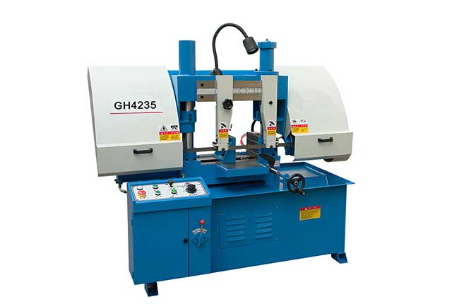
The main components of the sawing machine are the bed, column, saw beam and transmission mechanism, guide device, workpiece clamping, tensioning device, feeding frame, hydraulic transmission system, electrical control system, lubrication, and cooling system.
1. Base
The base is a box-shaped structure welded by a steel plate. The bed and column are fixed on it. There is a large space in the inner cavity of the base. The front left side is the electrical button control box, and the right side is the electrical switchboard box. The middle is welded by a steel plate. The hydraulic oil tank is equipped with a hydraulic pump station and a hydraulic pipeline. The right side is a cooling fluid tank and a water pump, and the bottom four corners have anchor bolt holes.
2. Bed structure
The bed is made of cast iron and fixed on the base. The column is composed of a large and small column. The large round column is used as a guide rail for the saw frame to ensure precise guidance. The small cylinder plays an auxiliary role to ensure the normal cutting of the saw blade. The middle is the clamping vise and manual feeding structure.
3. Saw beam and transmission mechanism
It is made of thick steel plate cut, formed, and welded, with strong rigidity. A worm gearbox is fixed on the right rear side. The worm wheel in the box is fixedly connected with the driving wheel on the saw beam, and the two rotate synchronously. The left side is the tension position of the driven wheel and the saw blade. The rotary motion of the saw blade is driven by the main motor, belt pulley, and worm gear through the two-stage transmission to the driving wheel, and then the driving wheel and saw blade drive the passive wheel to realize the saw blade running speed in three gears.
4. Saw blade guide device
The guide device installed on the saw beam support plate is composed of left and right guide arms and guide heads. Both the left and right guide arms can move along the dovetail (or the right guide arm is fixed on the column sleeve) to adjust the distance ratio between the two guide arms. The workpiece size is about 40mm wide. The guide device is used to change the installation angle of the saw blade so that the saw blade is perpendicular to the worktable. To ensure the cutting accuracy of the saw blade and reduce vibration, a set of guide wheels (rolling bearings) and wear-resistant guide blocks are installed on the left and right guide arms. Guide block of wear-resistant alloy.
5. Clamping mechanism
The right vise is fixed on the bed, the clamping screw passes through the inner hole of the hydraulic clamping cylinder, and the left vise is connected by the screw to move left and right along the guide rail, and is connected when the left vise is 10-30MM away from the workpiece. Press the clamp on the control panel or loosen the clamp to clamp or loosen the workpiece.